Naim Audio New Classic and Balanced Connections
The information below is from Naims issued white paper by Steve Sells, Electronics Technical Director at Naim Audio
Abstract
This paper discusses a brief history of balanced interconnection, pros and cons of the various methods, how it works and why and how it is implemented in the new Naim classic range.
Introduction
Balanced audio systems have their origins in telephony technology developed back in the 1920s, when analogue audio was sent many miles down copper cables hung from poles. Today’s balanced audio systems can be traced back to the valve mixing desks used in recording studios, such as the BBC, from the 1940s. Back then, studios would send audio from room to room, for example from the studio to the transmitter room or record cutting room. Audio sent over those distances could very easily pick up noise from other electrical systems, so balanced audio was introduced to dramatically reduce external interference.
By the 1950s, three-pin XLR connectors were developed by Cannon, and they remain the most common balanced connection design. The connectors have both male and female versions: the signal exits the male, and the signal input is on the female. This idiot-proof design prevents two outputs, or two inputs, being inadvertently connected.
The three pins are:
· X= ground
· L = live (or hot, non-inverted)
· R = return (or cold, inverted)
Note: XLR is a ‘backronym’. Cannon originally had an X-series of connectors, to which it added a locking Latch (becoming XL) then Resilient rubber insulation, with the XLR prefix in use from 1955.
Below shows the male and female XLR pinout, with its mirror image connections.

Balanced systems
Noise rejection
The diagrams below show the balanced signal as it leaves the source, goes down the interconnect cable, subsequently picks up noise and then has the noise cancelled in the receiver.
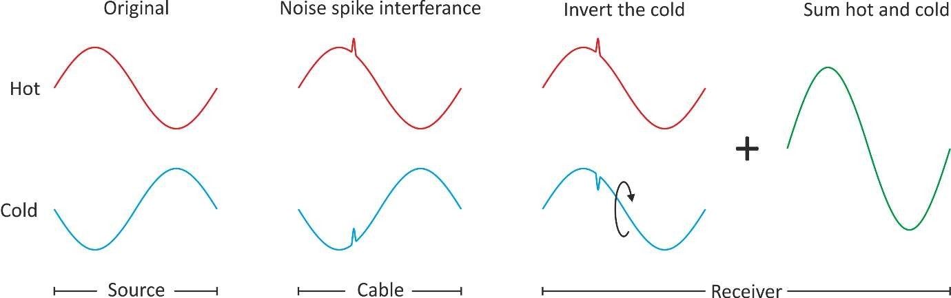
Noise rejection works by sending two versions of the same signal. One non- inverted (hot) and one inverted (cold). Should any noise be picked up, it will be equal and in-phase on both hot and cold. When the signal enters the receiving product, the cold signal is inverted again to make it non-inverted. Any noise that was present will now be out of phase with respect to the hot i.e., it is now equal and opposite. It will cancel with the noise on the hot signal when added. The signal will also be 2x bigger e.g., if each signal is 1 volt, then 1V + 1V = 2V.
Leakage current noise rejection
Ground leakage can manifest itself in two main ways. The most obvious is when a metallic non-earthed mains powered piece of equipment is touched leaving a tingling sensation in the fingers. The second is a smaller effect. Audiophiles know that the mains polarity of a product can affect sound quality. Changing the mains polarity affects a small AC current in the audio interconnect leads between equipment. This AC current produces a small AC voltage in the ground wire of the interconnect. This small AC signal is added to the audio signal and is detrimental. However balanced systems do not use the ground for audio, only the hot and cold are used.
Pseudo Balanced
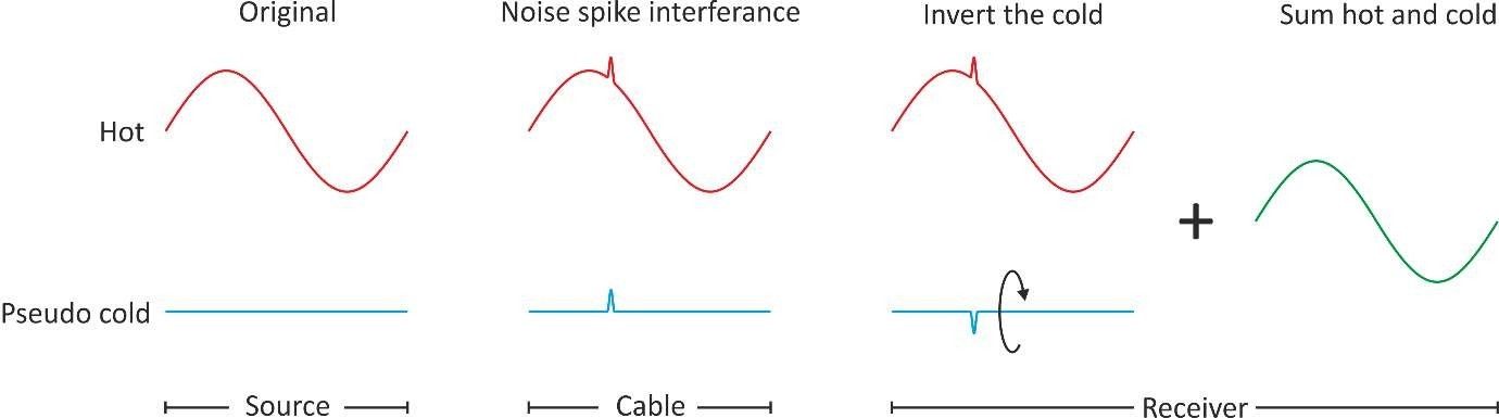
Below shows a ‘pseudo balanced system’ or ‘balanced impedance’ system. Here the cold has no signal, it does however have the same output impedance as the hot signal. By maintaining the same impedance, the noise pickup is identical on both signals. The noise rejection principle is the same as full balanced system and the end signal is the original amplitude.
A full balanced output uses two active circuits: one for hot and one for cold. A balanced impedance output uses one active circuit for the hot and only passive parts for the cold. The full balanced system would typically use two identical circuits for the hot and cold. Each circuit would produce the same distortions, however small. These distortions will be made from even and odd harmonics. When the receiving circuit inverts and adds the cold signal to the hot, the even-order harmonics will cancel, leaving only the odd-order harmonics. The removal of the even harmonics, such as ‘second harmonic’, can make the system sound harder. A balanced impedance system, having only one active circuit, will retain the even- order harmonics and the original sound character is maintained.
If a source product has both balanced and unbalanced outputs, some consideration will need to be given to relative output levels. For example, a bi-amp system using both the balanced and unbalanced outputs would have a 6dB error. This can be corrected by using a third circuit exclusively for the unbalanced outputs. A balanced impedance system has the same signal levels for both balanced and unbalanced. Comparing these systems, the level-matched balanced system will take three-times more current. Additional current can have an adverse effect on sound quality. Balanced impedance rejects noise and leakage currents the same as full balanced.
Balanced receiver circuits ‘electronic’ or ‘transformer’
Traditionally, small signal transformers were used for both generating the hot and cold signals and for receiving the hot and cold and converting to single-ended. This was because active components such as valves and transistors were very expensive. Transformers still have their place today. They are passive and require no power, should last 100 years, offer galvanic isolation between the source and receiver and have great noise rejection. However, they will distort the signal (though in moderation this distortion can be pleasing and is often deliberately used on mics in recording studios) and can also pick up hum. Electronic balanced circuits must be carefully designed to ensure good noise rejection and are typically more transparent. Electronics and transformer systems cam be mixed and matched.
600ohms vs low/high impedance
In the early days of balanced signals transmission, interfaces had a 600ohm impedance. 600ohms is the natural impedance of two very long conductors spaced apart, as per those original telephone lines where no insulation was used. By keeping the whole system the same, impedance signal reflections were minimised and maximum power transfer was achieved. This was only relevant when the signals travelled miles, but this legacy 600ohm impedance did find its way into studio equipment. High-end audio equipment uses low impedance on the source for good cable drive. The receiver then uses a high impedance so as not to load the source and cause distortion.
Balanced vs Bridged
Note: Bridged amplifiers use two amplifiers per channel instead of one. One amplifier is hot and the other is cold i.e., one channel is non-inverted and the other is inverted like a balanced system. An amplifier is bridged to give more power by increasing voltage swing and not bridged to reject noise.
New Naim Classic balanced connections
Overview
New Classic was conceived to be our most interoperable, easy-to-use range ever, with improved sound quality and clear upgrade paths. Using balanced connectivity was key to meeting the goal. All balanced inputs and outputs are via twin XLR connectors and are industry compatible.All source and pre-amp products in the range use balanced impedance outputs. They also have legacy single-ended outputs. Where included, balanced pre-amp inputs use electronic receivers. All power amp inputs are balanced using electronic receivers.
Naim pseudo balanced outputs
A new line driving/headphone amplifier stage was developed specifically to meet
strict criteria:
- Exceptional performance (benchmarked with 500 Series)
- Drive long cable runs, needed for remote power amplifiers
- Drive headphones to 1W (1.5W into 16ohms)
Naim electronic balanced inputs
A new electronic input receiver circuit was developed for power amplifiers. Balanced to single-ended converters are typically used, which can double the active electronics signal path compared to the original power amplifier circuit. To maintain the character of the original amplifier, the new Naim circuits are kept as simple as possible and powered by their own DR regulators. The circuit consists of two single-ended zero-feedback class-A buffers per channel: one for hot and one for cold. These then directly feed the main non-inverting and inverting inputs of the power amplifier circuit.
More complex electronic balanced circuits and balanced transformer coupled inputs were auditioned in the listening room. The class-A buffer prototype was added to a NAP 25ODR and it was preferred compared to a non-modified NAP 250DR. The pre-amp balanced input follows a similar vein. The same class-A buffers feed the first filter stage Naim discrete component op-amp circuits, which again adds very little to the overall signal path, while gaining the noise and leakage current rejection advantages of balanced designs.
Conclusions
Naim has chosen balanced impedance source and pre-amp outputs and fully electronically balanced inputs on pre-amps and power amps throughout its new Classic range. Pre-amps still have single-ended DIN inputs and single-ended outputs for compatibility with legacy products.
Advantages of balanced inputs
- Allows consolidation of inputs across the range of power amplifiers
- Allows flexibility of installation location (e.g., amps by speakers) thanks to noise rejection
- Balanced is the industry norm for high-end power amplifiers
- Uses industry standard XLR to XLR leads
- Super-tuned simple electronic balanced inputs are used for speed and transparency.
Advantages of balanced impedance outputs
- Retains the sound character of the original circuits
- Ensures current consumption is kept to a minimum
- Keeps levels of single ended and balanced the same for simplicity of system building.
Legacy compatibility
A range of cables have been created to allow connection to and from legacy systems — these are detailed in our dedicated Compatibility & Cable Information Guide.
LVDS - Digital balanced
On a side note: LVDS is ‘low voltage differential signalling’. Naim uses LVDS on its streaming products to send high-speed digital audio from PCB to PCB and for long PCB traces. This minimises stray electromagnetic fields. Lowering noise in a product helps keep the analogue outputs clean of RF interference, which is detrimental to sound quality